In recent posts we have comprehensively discussed inflation meshing requirements for resolving or modeling wall-bounded flow effects due to the turbulent boundary layer. We have identified the y-plus value as the critical parameter for inflation meshing requirements, since it allows us to determine whether our first cell resides within the laminar sub-layer, or the logarithmic region. We can then select the most suitable turbulence model based on this value. Whilst this theoretical knowledge is important regarding composite regions of the turbulent boundary layer and how it relates to y-plus values, it is also useful to conduct a final check during post-processing to ensure we have an adequate number of prism layers to fully capture the turbulent boundary layer profile, based on the turbulence model used (or more precisely, whether we aim to resolve the boundary layer profile, or utilize a wall function approach). In certain cases, slightly larger y-plus values can be tolerated if the boundary layer resolution is sufficient.
How can I check in CFD-Post that I have adequately resolved the boundary layer?
For the majority of industrial cases, it is recommended to use the two-equation turbulence models, or models which utilize the turbulent viscosity concept and the turbulent viscosity ratio (i.e. the turbulent viscosity over the molecular viscosity). We can make use of this concept to visualize the composite regions of the turbulent boundary layer, and ultimately visualize how well we are resolving the boundary layer profile. Consider the conceptual case-study of the turbulent flow over an arbitrarily curved wall. Prism layers are used for inflation, and tetra elements in the free-stream. Once we have calculated the solution, within CFD-Post we can create an additional variable for the eddy viscosity ratio. Then by plotting this variable on a suitable plane, and superimposing our mesh in the near-wall region, we can visualize the boundary layer resolution.
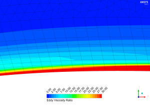
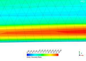
Figure 1 provides an example of a reasonable wall function mesh. There is a good cell transition from the prisms to the free stream tetra elements. The y-plus we have prescribed at the first cell indicates we are in the logarithmic composite region of the turbulent boundary region, which is the region largely dominated by inertial forces and thus we have high levels of turbulence. The turbulence gradually dissipates as we approach free stream conditions (where the levels of turbulence are governed by inlet conditions), which is expected. At this stage, we could even reduce the number of cells in the inflation layer as we are clearly capturing the logarithmic region layer before approaching the free stream. Correspondingly, we could aim to reduce the y-plus value (y-plus ~ 20) to better capture the increase in turbulent viscosity as we move from the inner layer to the outer layer of the logarithmic region.
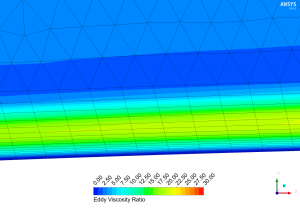
Figure 2 provides a good mesh for a low-Re turbulence model. We observe that the transition in size from the final prism layer to the free stream tetra elements has been regulated well. Since we have prescribed a y-plus value of 1 we are within the laminar sub-layer, which exhibits laminar flow characteristics (thereby resulting in no turbulent viscosity). As we gradually move through the buffer region and into the logarithmic region we see a large rise in the viscosity ratio before it dissipates into the free stream. This maximum value will generally occur near the middle of the boundary layer, which also gives us an indication of the physical boundary layer thickness (twice the location of the maximum eddy viscosity ratio gives the boundary layer edge). As per the example given in Figure 2, it is essential that the prism layer is thicker than the boundary layer as otherwise there is a danger that the prism layer confines the growth of the boundary layer.
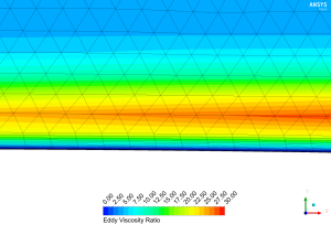
Figure 3 ia an example of a poor quality mesh for a low-Re turbulence model (such as SST k-omega). In this case we have unnecessarily prescribed a very low y-plus value yet we have not compensated by appropriately allowing for more prism layers in the inflation layer. Therefore, we are capturing the laminar sub-layer to an excessive detail, and the boundary layer does not transition to the logarithmic region until we are well inside the free stream. Consequently there are cells which are not aligned with the direction of the flow and thus our boundary layer profile will not be well resolved (its growth may be confined by the extent of the prism layers), hence affecting our drag or pressure-drop calculations.
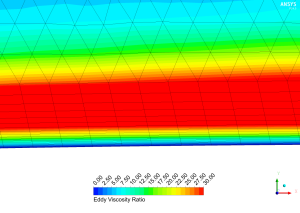
Figure 4 is an example of a poorly defined mesh for a standard wall function turbulence model. The accuracy of wall function or high-Re turbulence models (e.g. the k-epsilon variants) cannot be confirmed modeling the laminar sub-layer and thus should be avoided. In ANSYS Fluent, the laminar stress-strain relationship is employed when the mesh is below a y-plus of 11.225 (noted as the transition to the logarithmic region). After which, the logarithmic wall functions are employed. This is an example where a low-Re turbulence model should be used (c.f. Figure 2), or alternatively we could aim to increase our y-plus value such that it resides in the logarithmic region (c.f. Figure 1).
The problems in Figure 4 can be overcome using scalable wall functions, as shown in Figure 5 using the same mesh. The purpose of scalable wall functions is to force the usage of the logarithmic law. Here we can see a turbulent viscosity distribution which is analogous to the case presented in Figure 1 (with the exception that we are now capturing the increase in turbulent viscosity as we move from the inner layer to the outer layer of the logarithmic region). For this simple case, we could potentially save simulation time by coarsening the mesh immediately adjacent to the wall, or alternatively we could opt for a low-Re turbulence model. The real advantages of the scalable wall functions arise for complex flows on grids of arbitrary refinement (or correspondingly flows with various boundary layer scales) since it will provide consistent modelling.


