Our previous blog introduced the concept of an Adjoint solver and described how adjoint solutions can be used to automatically optimise the performance of your device or process. Building on this, let’s now delve a little deeper… starting with acknowledging the limitations of the Adjoint solver in its first implementation, and how key new features in ANSYS Fluent v17 and v18 have now allowed the Adjoint solver to handle more practical user scenarios and a broader range of physics.
When we first showed the Adjoint solver to our customers, they commonly had 2 reactions (in this order):
- “Wow, that is cool and could really make my life easier and improve my designs…”
- “BUT (!) it won’t work for me if you can’t:
- Stop it from suggesting designs that are not manufacturable; and/or
- Constrain the optimisation process to only occur within specified zones (ie. respect packaging constraints); and/or
- Keep the shapes of key components fixed, but still allow the Adjoint solver freedom to move their position”.
Well, the development team at ANSYS have listened to all of this feedback and the latest releases of the Adjoint solver have focused solely on improving the usefulness of the Adjoint solver for real-world customer problems - allowing for definition of multiple objectives; expanding to include more physics; and allowing more user control over geometry modifications and constraints.
Multi-objective optimisation in Adjoint Solver:
“How can I balance my design trade-offs and account for multiple objectives with the Adjoint solver?”
The Adjoint solver now allows for a broad range of observable types to handle many more industrial problems. In addition to forces, one can specify pressure drop, swirl, surface and volume integrals as observables to be optimised in the design. The user can also create compound observables by combining existing ones using unary operations like ratio, product, arithmetic average etc. For internal flows, the Adjoint solver can be used to reduce total pressure loss and increase the flow uniformity of the outflow velocity profile.
More control over geometry changes in Adjoint solver:
“How can I control where the Adjoint solver makes changes or constrain it to only move/translate/scale my existing geometry?”
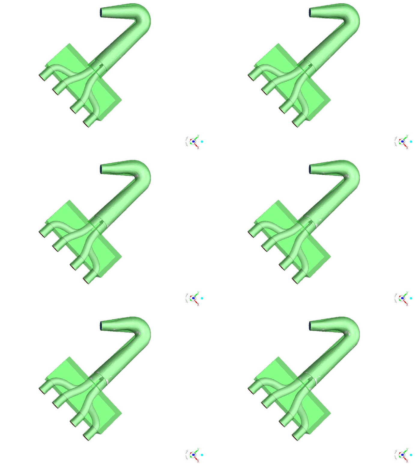
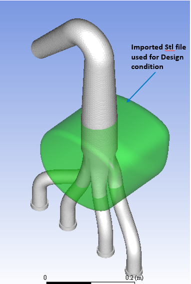
Although the Adjoint solver calculates sensitivities for the whole domain for a given observable, the user can now limit any geometry modifications to specific regions of the domain within a complex zone – using an imported STL file. In most cases, the component being optimized is a part of a bigger system and has various constraints on regions that can be modified and regions that need to be fixed. In such instances, one can go to the design conditions tab to specify a design condition such as “fixed walls”, “bounding planes”, “bounded-by-surfaces” etc, for the optimized design to adhere to the design conditions.
Another useful new feature allows users to specify surfaces that can undergo rotation or translation to improve your design objectives. This feature will allow re-positioning and re-orienting of existing parts within in a larger assembly - to improve overall efficiency of the design without actually changing the geometry of these “standard” parts (which may be chosen for reasons of cost or manufacturability). Surfaces can also be scaled by applying a scale factor along a coordinate axis or a normal direction to allow the Adjoint solver to determine the optimum size required to improve the system performance.
More physics supported in Adjoint Solver:
“How can I use the Adjoint solver for problems involving rotating domains or conjugate heat transfer?”
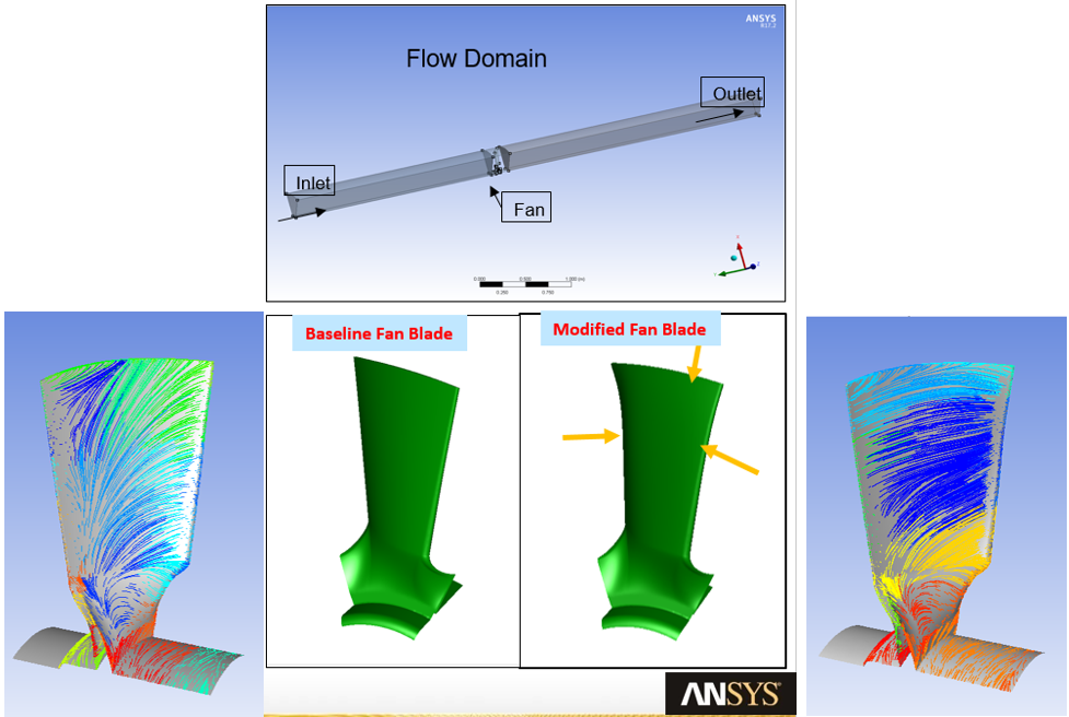
The flow physics supported by the Fluent Adjoint solver are being increased each version to help designers from a wide range of industries optimize their products in a better way. Periodic problems can be now analysed using this solver along with problems containing porous zones. In the latest release, problems involving moving reference frames can be tackled along with problems containing conjugate heat transfer. These new features make Adjoint solver a useful tool for challenging problems like fan design, as shown below.
In the above example, the objective of the optimization is to improve the efficiency of the fan by reducing the total pressure increase in the stage and reduce the torque and power required to drive the required mass flow through the stage. In this case, recommendations automatically generated by the Adjoint solver increase the fan efficiency by 8.5%.
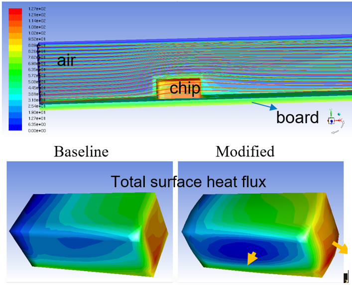
Allowing Adjoint solver to handle Conjugate heat transfer problems allows us to define the heat transfer on a surface as an observable in such problems. This is extremely useful in improving chipboard cooling designs where subtle changes in geometry identified by the Adjoint solver led to a 7.5% increase in the amount of heat transferred through the cooling surfaces when compared with baseline design.
As the above examples illustrate, the Adjoint solver can now be used on a wider range of problems to improve your product performance.
Other useful notes on Adjoint solver:
When using multi-objective optimization, the user can export sensitivity data for each observable combination that takes part in the optimization. This is done through the region tab of the design tool after the deformation region is specified. The exported file contains the sensitivities of the observable for the mesh nodes within the specified deformation region.
Once the bounding box and the design conditions are specified for the Adjoint solver, a design change can be calculated which calculates the expected change of the observable in the modified design. This expected change can be written to a file for future reference along with a separate file containing the surface displacements field for the new design. This feature is useful for version control of various design changes.
These design changes can be applied to the geometry by clicking on modify mesh. It is possible to revert to the initial geometry if the user is not happy with the suggested modifications. Upon successful modification of the geometry, the user can export the new surfaces as STL files to recreate the new design in other software packages.
As with most features within Ansys Fluent, all the commands within the Adjoint Solver workflow have counterparts in the text user interface. The iterative nature of Adjoint solver runs make it attractive to run via a Fluent journal file.
This concludes our update on improvements to the ANSYS Fluent Adjoint solver. Readers are encouraged to contact support at LEAP Australia for specific information on best practices for setting up the Adjoint solver and for help in implementing these new features for a specific project.


