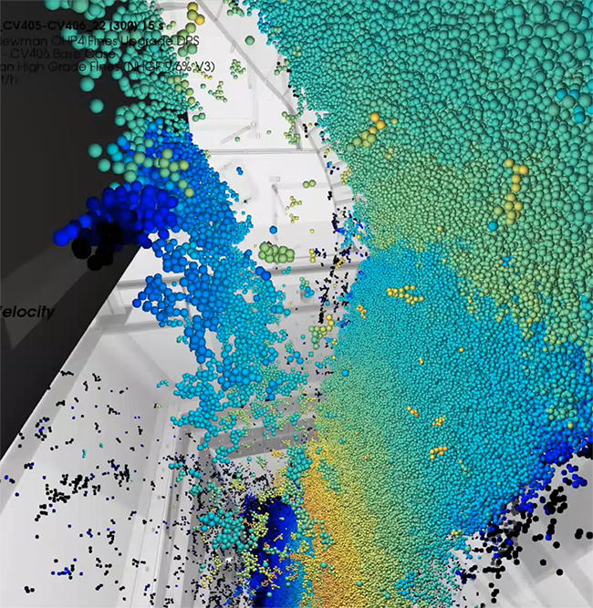
Rocky DEM is a high fidelity particle simulation program that quickly and accurately simulates particle behaviour within bulk materials handling systems used across a variety of industries including mining and minerals processing, food and beverage, pharmaceutical, agricultural and any industry dealing with particulate systems or solids handling applications.
Some keys features include:
- an extensive library of realistic particle shapes,
- an intuitive and easy-to-use interface,
- superior scalability with CPU, GPU and multi-GPU processing,
- advanced breakage and flexible particle models,
- evaluation of belt and surface wear,
- integration with ANSYS FEA and CFD,
- complex moving and vibrating boundaries and more.

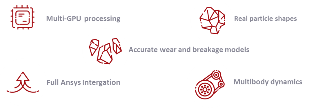
Figure 1: Advanced Unique Capabilities of ROCKY DEM
In this article, we will focus on materials calibration which is a process commonly adopted in DEM to fine-tune material contact parameters in order to match physical testing. This is an important and often overlooked step in DEM, not only to ensure good solution accuracy but to be able to predict potential problems such as belt wear, blockage and spillage and to tailor a design which is optimal and not prone to failure. This is where DEM simulation adds real value to industry.
So why do we need to calibrate? Garbage In, Garbage Out or GIGO, can best describe what happens if we merely bypass the calibration step by guessing or assuming material parameters. So this begs the next question, namely, why don’t we just have a library of materials like we do in FEA or CFD for example? Unlike CFD or FEA, there is no standard library of materials in DEM since the variability in a bulk solid is far greater than standard materials we usually encounter in the world of fluid or structural mechanics (e.g. water, steel etc.).
Shape, size, density, friction, adhesion are just some of these DEM parameters that can vary substantially even within the same bulk solid. Furthermore, external environmental conditions such as temperature and humidity can also affect the way a material flows. Whilst this may sound somewhat overwhelming and time consuming especially for the first time, the calibration process becomes progressively faster and more streamlined as we repeat this process and build up a database of different materials, providing us with a complete matrix of input parameter combinations. Also important to note that whilst there is variation between individual particles and inherent idealizations or simplifications made in the simulation, mainly for ease of computation, it is the macroscopic bulk flow behavior that it important to capture rather than microscopic individual particle interactions.
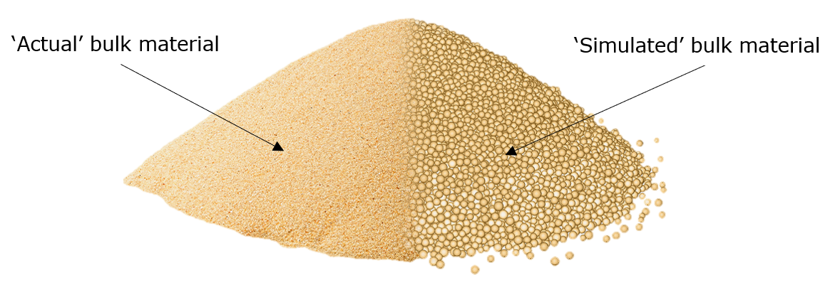
Figure 2: Matching the Static Angle of Repose with a Bench-top Test
New Calibration Suite inside ROCKY DEM
Rocky DEM has provided both new and existing users with access to a new calibration suite. This suite consists of a series of ‘standard’ tests, most of which can be conducted on a bench-top at lab scale. These tests are usually conducted under carefully controlled conditions to ensure repeatability and reproducibility. This is an important aspect of testing as it is very rare that the same test will yield identical results, so it is important to repeat the test several times and extract statistically reliable values or a range consisting of a mean and standard deviation.
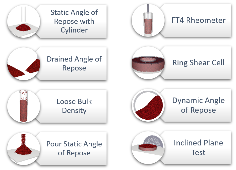
Figure 3: ROCKY DEM Calibration Suite
The tests described above have predefined Pre- and Post-processing scripts which provide high-level automation for the user with just a few mouse clicks, thus greatly simplifying the workflow for the end-user. They are designed to be used straight ‘out of the box’ however can modified and customised by the user to suit their specific requirements. Usually there is no need to run all eight tests for each material as some are specifically designed for free-flowing or cohesive materials and others are more suited to powders and fines rather than lumps or primary crushed ore as highlighted in the table below.
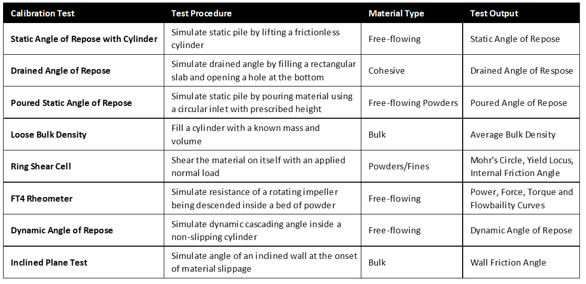
Figure 3: Summary of ROCKY DEM Calibration Tests
Finally, whilst there is no right or wrong test when it comes to materials calibration, the key point is that the numerical calibration test closely resembles the physical test to ensure similar flow conditions. Moreover, thought must be given to the flow conditions of the system to be simulated and the corresponding properties that are important in characterising this type of flow. For example, the consolidation pressures in a chute may be different to those present inside a bin or hopper so a static angle of repose test alone is usually not a reliable means of calibration since it does not consider the bulk solid in motion under higher consolidation loads, as say with a ring or Jenike direct shear tester.
Access our case study which includes a 30 minute on-demand webinar in which LEAP and Rocky DEM customer Onyx Projects detail how they calibrated iron-ore to predict flow trajectories and wear patterns inside a transfer chute.
Want more info?
For more information or to discuss your application, contact us by completing the form below. The calibration suite is available for download from the customer portal. Each test has an accompanying ‘Readme.txt’ file with a description, some guidelines and instructions.


