Engineers who are tasked with designing heating, ventilation and air-conditioning (HVAC) systems for buildings will need to assess the indoor air quality to ensure optimum health and comfort for occupants and meet minimum regulatory requirements. Generally a HVAC CFD analysis will take into account variables such as air temperature, relative humidity, air species concentrations and velocity. Additionally, CFD engineers can use ANSYS CFD to solve for the local "mean age of air" (MAA) to assess the air quality within an indoor environment. By examining MAA across the habitable space within a building, engineers can quantify the air change effectiveness (ACE) of their ventilation system and confirm that their design meets NABERS/GreenStar regulations.
How can I plot the Mean Age of Air in ANSYS CFD-Post?
Usually designers are interested in local distributions, therefore it is useful to plot the ACE as the ratio between the nominal time constant and the age of air or its inverse. Within ANSYS CFD-Post, it is possible to calculate the ACE at a specified height with a simple expression defined using CEL.
This allows us to quantify the area occupied by air with an age exceeding the mean value across a reference surface (typically located at breathing height, ie. 1m above floor). According to many regulatory standards, the area exceeding the target value must be less than 5%.
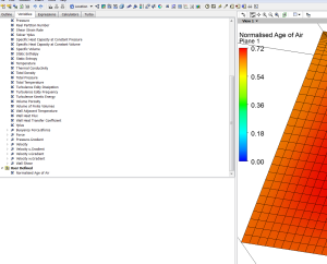
AgeofAir = Scalar 0 [s] and then creating a new variable which by definition is equal to AgeofAir.
Clipping the Age of Air to a specific range of values
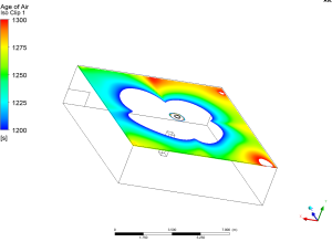
This is useful to quantify the size of any pockets of air that may exceed our target MAA value (ie. the value prescribed by regulations). In order to visualize the air which is older than this nominal value, we create an iso-clip for a value greater than the target value, applied to a plane located at a specified height above the floor (typically 1 metre).
The result should look similar to the one shown in the image below. The "holes" are regions where the MAA values are above or below the threshold specified in your iso-clip setup (in this case, anything below 1200 secs and above 1300 secs).
It is then straightforward to create an expression that quantifies the % area of the iso-clip to the full area of the plane. Typically engineers aim to ensure that this does not exceed 5% (according to the ACE 0.95 criteria). In this example the CEL expression would be written as:
Ratio = area()@Iso Clip 1/area()@Plane 3
How do I calculate mean age of air in my ANSYS CFD simulation?
The mean age of air (MAA) is not automatically included as a predefined variable in general purpose CFD software, such as ANSYS CFX and ANSYS Fluent. It can be defined in the pre-processing stage as an additional variable using the methods outlined below. This section provides some background and further details on how to include the MAA variable in both ANSYS CFX and ANSYS Fluent.
Some background...
The mean age of air, denoted , is obtained by solving the following advection equation:
The derivative with respect of time of the source is 1 so that the integral itself is time. When integrated, the age scalar will equal the residence time.
In ANSYS CFD solvers, scalar quantities are multiplied by the density in the transport equations, so that is in this particular case the equation to use is:
The term on the right hand side of the equation is known as the source term, and it has to be taken into account when implementing the mean age of air variable in the simulation.
According to the ACE 0.95 criteria for modern building regulations, for instance, the displacement air within the enclosed environment has to provide an air change effectiveness (ACE) higher than 0.95 for at least 95 % of the net lettable area (NLA) when measured in accordance with ASHRAE 129-1997.
Air change effectiveness is defined as the ratio between the nominal time constant and the average of the age of air at a reference height
The nominal time constant is the ratio between the air volume of a space or building divided by the rate of outdoor air supply, which is the incoming volumetric flow rate. Mean residence time
The reference surface is taken at 1 [m] above the floor to consider the breathing zone of the enclosed space.
ACE gives a measure of the distribution of air at the breathing height and a value close to unity indicates that the air distribution within the zone has reached perfect mixing. According to the GBCA’s Green Star requirements of IEQ-2 version 2, a well designed ceiling air diffusion system will achieve an ACE of near unity (between 0.8 and 1.2) at design air flow rates. A displacement ventilation system typically achieves an ACE of greater than 1.2.
How to define the variable "Age of Air" in ANSYS CFX:
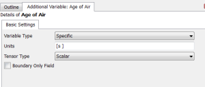
To calculate the age of air, it is necessary to create a new variable under the Expression, Functions and Variables tree in CFX-Pre. In this example the new variable has been named Age of Air . It has units of seconds.
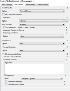
CFX solves a transport equation for the newly created variable . This is shown in the Fluid Models tab of the default domain, under the Additional Variable Models. As the age of air does not diffuse, it is not necessary to define a Kinematic Diffusivity for it. Note, that in ANSYS CFX, turbulent diffusion is included by default.
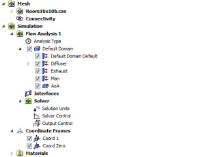
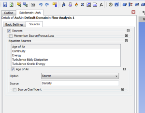
As the transport equation is of type 'specific', it is necessary to add a source term equal to the fluid density. This is done by creating a sub domain (here named AoA), under the Default Domain and defining the 'Source' to be density as below.
The last step in ANSYS CFX is to set a value for Age of Air at any boundary conditions where air can enter the domain. In this example, the Age of Air at the diffuser and at the exhaust (for any return flow) has been set to 0 [s]. It is also possible to specify non-zero values if recycled air is used.
How to define the variable "Age of Air" in ANSYS Fluent
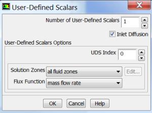
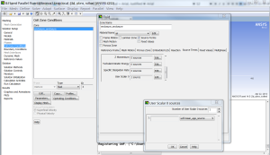
In the previous section we've described the method to include an additional variable (in the form of a transport equation) for calculating the age of air in ANSYS CFX. Similarly, in ANSYS FLUENT we can calculate the age of air through use of a user defined scalar (UDS). This involves creates a user defined scalar for the age of air then solving its equation after a solution for the flowfield has been obtained.
The following UDF computes the diffusivity to account for turbulent diffusion (which is not implicitly defined as in CFX) and the source for the mean age of air. This function can be executed as an interpreted or compiled UDF.
#*******************************************************************
#include "udf.h"
#include "prop.h"
#This define the AoA diffusivity
DEFINE_DIFFUSIVITY(mean_age_diff, c, t, i)
{
return C_MU_EFF(c,t)/0.7
}
#This defines the source
DEFINE_SOURCE(mean_age_source, c, t, dS, eqn)
{
real source;
source = C_R(c,t);
dS[eqn]=0;
return source;
}
#********************************************************************
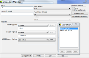
After the UDF is interpreted or compiled, the name specified in the DEFINE macro argument (e.g., mean_age_diff) will become visible and selectable in the Create/Edit Materials dialog box in ANSYS FLUENT
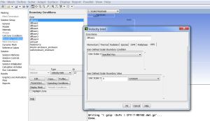
Finally it is necessary to set a boundary condition for the scalar at all inlets and outlets. In this example uds-0 scalar values = 0 at the inlet (but, as in CFX, can be set at a non-zero value if desired). The setup for the new variable for mean age of air in FLUENT is now complete.
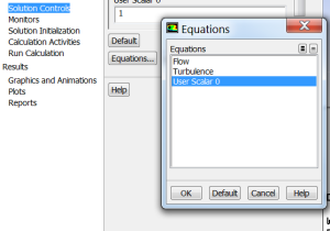
The User Scalar 0 in the Solution Controls panel . By selecting it the solver will calculate a solution only for the UDS.
This post has aimed to provide an overview of the age of air parameter in CFD, and some tips on how to create and post-process the results for mean age of air in ANSYS CFD. CFD simulations of this type are increasingly being performed by building designers and engineers to both meet stringent building codes and help differentiate the sustainability and liveability aspects of their design. To this effect, ANSYS CFD provides engineers with a valuable tool to assess the levels of thermal comfort for building occupants, by examining parameters such as the air temperature and radiant heat loads, as well as a tool to ensure adequate air change effectiveness by solving and assessing the mean age of air. For further information or to discuss your own CFD problem within HVAC industry, please leave a comment below.


